If you’re in the market for turned parts—whether for automotive, medical, aerospace, or even that niche custom robotics project you’re building—you know that precision isn’t just a buzzword. It’s the difference between a part that slots seamlessly into an assembly and one that brings your whole line to a halt. As a precision turned parts supplier, I’ve seen firsthand how easy it is to cut corners when measuring parts, especially when you’re juggling tight deadlines. Over the last 12 years, I’ve worked with everything from tiny medical implants that need to fit with 0.0002-inch tolerance to larger industrial components that have to align perfectly across 12 feet. Today, I’m breaking down how we measure turned parts accurately, the mistakes I see even seasoned teams making, and the tricks we use to make sure every part leaving our shop is actually up to spec. Precision Turned Parts
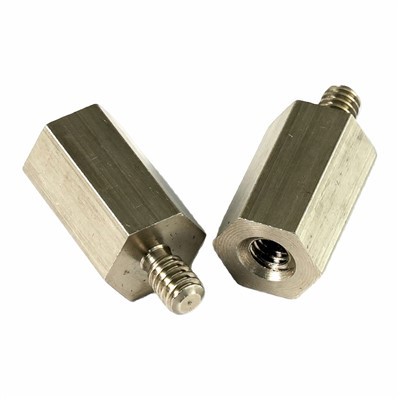
Let’s start with the basics: what actually counts as precision for turned parts? You’d be surprised how many people mix up “close tolerance” with “accurate measurement.” Turned parts are made on lathes, where a bar of material spins while a cutting tool shapes it. The key measurements here are usually diameter, length, concentricity, surface finish, and sometimes runout. But here’s the thing: a measurement is only as good as the tool and the process you use to take it. Grab a random caliper from your toolbox and snap a reading? That’s fine for rough parts, but not for anything that matters. I’ve lost count of times a client sent us a part they measured with a $10 Amazon caliper, claiming it was “off” by 0.001 inch—turns out their caliper was out of calibration by 0.003 inch. Calibration isn’t a one-and-done task, either. If a tool gets dropped, banged around, or even moves between temperature extremes (like from a 70°F office to a 90°F shop floor), its calibration drifts. We calibrate every single one of our measuring tools—from micrometers to CMMs—every 90 days, plus after any heavy use or impact. It’s an extra step, but it’s non-negotiable.
Next up: choosing the right tool for the job. I know, it sounds obvious, but you’d be shocked how many people use a one-size-fits-all approach. Let’s talk about the most common measurements first. For external diameters, micrometers are still the workhorse, right? But not just any micrometer. If you’re measuring a part with a curved or non-round surface, a standard flat-anvil micrometer will give you a false reading—because it’s not accounting for the contour. We use spherical-anvil micrometers for parts like surgical pins or valve stems, since they conform to small, curved surfaces. For internal diameters, a bore gauge is way more accurate and faster than trying to snap a caliper inside a hole. Wait, but not just any bore gauge—for deep bores, we use a telescoping gauge paired with a micrometer, because a small hole that’s 6 inches deep will flex if you stick a rigid bore gauge in it, throwing off the reading. And for really tiny parts—like those 0.05-inch diameter pins for insulin pumps—we use a laser micrometer. It’s non-contact, so it doesn’t scratch the soft material (like titanium or PEEK) we use for medical parts, and it can take readings every millisecond, so we capture multiple points across the part instead of just one. That brings me to my next big point: you can’t just measure one spot on a turned part.
Turned parts spin on a lathe, so their cross-section isn’t always a perfect circle. Wait, why would that happen? Even the best lathes have a tiny bit of runout, or the material might have a slight imperfection, or the cutting tool might wear just a fraction over the length of the part. If you measure only the very end of a 2-inch long shaft, you might think it’s perfect, but the middle could be 0.0005 inch smaller—enough to make it wobble when installed. That’s why we do multiple measurements: for diameter, we take readings at the start, middle, and end of the part, both along the horizontal axis and vertical axis. For concentricity—how well the internal bore aligns with the external diameter—we use a coordinate measuring machine (CMM) for larger parts, or a micrometer with a rotating anvil for smaller ones. A lot of suppliers skip the multi-point check to save time, but I’ve had so many clients come back with parts that “fit fine on the lathe but not in the assembly” because they only checked one spot. Last year, we had an automotive client almost miss their launch because their old supplier only measured the end of a transmission shaft, and the middle was off, causing a vibration that would’ve failed crash tests. That’s the kind of mistake we avoid at all costs.
Surface finish is another big one that’s often overlooked, especially for high-precision parts. Turned parts have a “feed mark”—the tiny spiral left by the cutting tool as it moves along the part. For aerospace parts, that feed mark might be fine, but for medical implants that sit in the body, a rough surface can harbor bacteria or cause irritation. We measure surface finish using a profilometer, which drags a tiny stylus across the part and maps the peaks and valleys. The key here is to set the right “cutoff length”—that’s the distance the stylus travels to get an accurate reading. If you use too short a cutoff, you’ll only measure the tiny, random scratches and miss the overall feed mark; too long, and you’ll pick up the curvature of the part itself. For most turned parts, we use a cutoff length of 0.03 inch, which works for both small and medium components. A lot of smaller shops use a “touch and feel” for surface finish, but that’s totally subjective—one machinist might think a part is smooth, while another might see it as way too rough. The profilometer gives us a numerical value (Ra, or average roughness) that’s consistent every time.
Wait, what about environmental factors? That’s something a lot of people forget when measuring parts. Steel expands when it’s warm, shrinks when it’s cold. If you bring a part straight from the lathe (where it’s 150°F from the cutting process) into your temperature-controlled measurement room (which is set to 68°F), it’ll take at least an hour to stabilize. If you measure it right away, you’ll get a reading that’s 0.001 or more off, depending on the size of the part. We have temperature probes in our measurement room, and we wait until every part is within 0.5°F of room temp before we touch it. Even better, we store all finished parts in the measurement room for at least two hours before inspection, so we never have to rush that step. I’ve had a client bring us a batch of parts they measured at their shop, which was 85°F, and their readings were all 0.002 inch smaller than they actually were—because the parts were still warm. That’s why cross-checking is so important too.
Cross-checking is non-negotiable for us. We never rely on one tool or one inspector. If a part measures right on spec with a micrometer, we’ll double-check it with a bore gauge or a CMM, just to make sure there’s no bias or tool error. We also rotate inspectors every week, because even the best inspector can get complacent if they’re measuring the same parts all day. Last year, a new inspector noticed a pattern in our measurements that the veteran team had missed—our lathe was wearing a cutting tool a tiny bit faster than we thought, so we adjusted our tool change schedule and avoided a whole batch of bad parts. That’s the kind of team effort that makes measurements accurate.
Now, let’s talk about the common mistakes I see all the time, because avoiding these is half the battle. First, overestimating your tool’s accuracy. That $500 digital micrometer might look fancy, but if it’s not calibrated, it’s no better than a $10 analog one. Second, not accounting for part deflection. When you measure a thin, long part, even pressing a little too hard with a micrometer will bend it, making the diameter seem smaller than it is. We use a light, consistent pressure on all tools—most of our micrometers have a ratchet stop that clicks when you reach the right pressure, so every measurement is the same. Third, ignoring the full profile of the part. As I mentioned earlier, turned parts aren’t perfect circles, so measuring only the “high spot” will give you a wrong diameter. Fourth, rushing the measurement process. Deadlines are real, but a bad part is way more expensive than a few extra minutes of inspection.
At the end of the day, accurate measurement isn’t just about using fancy tools—it’s about having a process that’s consistent, and not cutting corners. Every part we ship has a full inspection report that shows all the measurements: where we measured, what tool we used, the temperature when we measured, and the inspector’s name. Clients love that they can trace every number back to a specific person and tool, which builds trust. If you’re working on a project that needs precision turned parts, don’t just ask a supplier “what’s your tolerance?” Ask them how they measure that tolerance. Ask about their calibration schedule, how many points they check per part, and if they have cross-checking processes. That’s the stuff that separates the good suppliers from the ones that will send you parts that don’t fit.

If you’re tired of dealing with turned parts that are “almost right” or require constant rework, let’s talk. We specialize in high-precision turned parts for every industry, and we’ll work with you to make sure every part meets your exact specs—no surprises, no guesswork. Just reach out, and we can walk you through our inspection process, or even send over a sample of a part you’ve been struggling to get right.
Aluminum Turned Parts References
- ASME B89.1.13-2015, Measurement of Dimension and Geometric Characteristics of Machined Parts
- Groover, M. P. (2020). Fundamentals of Modern Manufacturing: Materials, Processes, and Systems (7th ed.). Wiley
- ISO 10360-2:2009, Geometrical product specifications (GPS) — Acceptance and reverification tests for coordinate measuring machines (CMM) — Part 2: CMMs used for measuring linear dimensions
- Chemical and Pharmaceutical Engineering, 2021, Vol. 57, No. 3, "Surface Finish Measurement for Precision Machined Medical Components"
Huizhou Quanyi Precision Hardware Products Co., Ltd.
Address: Building A10, 7th Floor, Zhongchuangyingke 5G Industrial Park, Zhonghan Industrial Park, Tonghu Town, Huizhou City
E-mail: info@qycncturning.com
WebSite: https://www.qycncturning.com/
